Laser connections
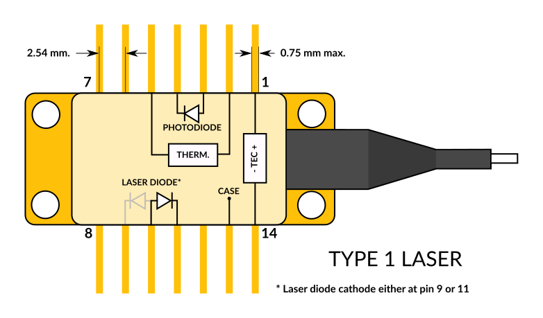
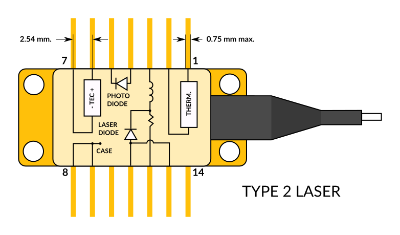
The CTL300E-1 / CTL300E-2 is compatible with Type 1 / Type 2 butterfly laser diodes. Note that it is only compatible with floating diodes.
Connector
The CTL300E mates with the TB300 breakout board.

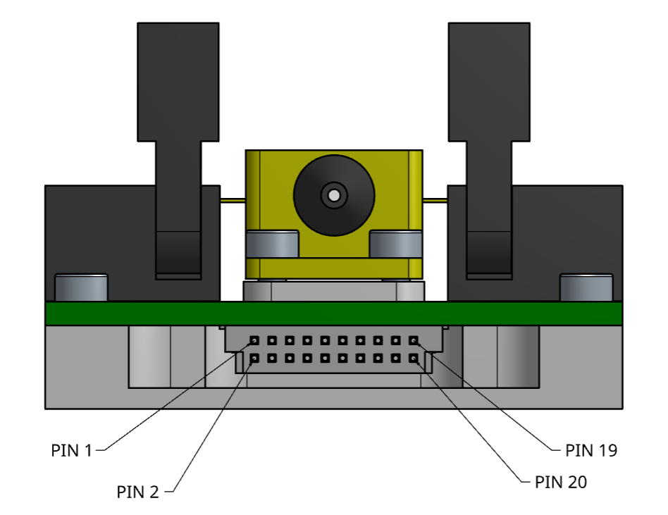
- VCC: (pins 17, 18 and 20) Input power supply from 6 V to 33 V.
- RFIN: (pin 4) Modulation input with ±1 V range and 50 Ω impedance.
- ALM: (pin 5) Alarm output (3V3 logic).
- DIO: (pin 7) Digital Input/Output (3V3 logic).
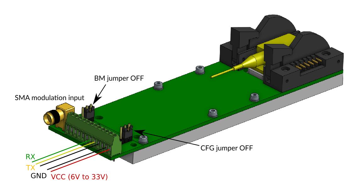
- CFG: (pin 8) Configuration input (3V3 logic, internally pulled-up to 3V3 with 100 kΩ). If CFG is HIGH at start-up, the board will start with the user-defined configuration. Otherwise, the default configuration is loaded.
- BM: (pin 9) Digital Input (3V3 logic, internally pulled-up to 3V3 with 100 kΩ). This pin is used for firmware update. Leave this pin unconnected or drive this pin high for normal operation.
- LCK: (pin 10) Interlock pin (see Interlock).
- TX: (pin 11) UART TX pin.
- BSEL: (pin 12) Bias selection pin (see Bias switching). This pin is internally pulled-low with a 100 kΩ resistor.
- RX: (pin 14) UART RX pin.
- AIN: (pin16) Analog input with a voltage range between 0 and 2.5 V. The voltage at the pin AIN can be retrieved with the ain command.
Connector mates with Samtec references FSH-110-04-L-RA-SL and FSH-110-04-L-DH-SL.
Serial interface
The serial interface can be accessed via TX and RX pins on the 20-pin connector (3V3 logic level / 5V tolerant). The serial interface is the only way to configure the CTL300E operating parameters. Once the configuration is done, it can be saved to the internal memory with the save command. If the CFG input is HIGH at start-up, the CTL300E will load the user-defined configuration and the serial interface is no longer needed.
The CTL300E can be controlled directly from a serial port terminal (e.g. Teraterm on Windows) with the following configuration:
- Baud rate: 115200
- Parity: None
- Bits: 8
- Stopbits: 1
- Flow control: None
Example use of the serial port terminal
>>
>>version
V0.2
>>rtset
10000.000000
>>rtact
10000.023438
>>rtset 12000
12000.000000
>>rtact
11999.853516
Note: Each command must be followed by \r\n.
Graphical User Interface
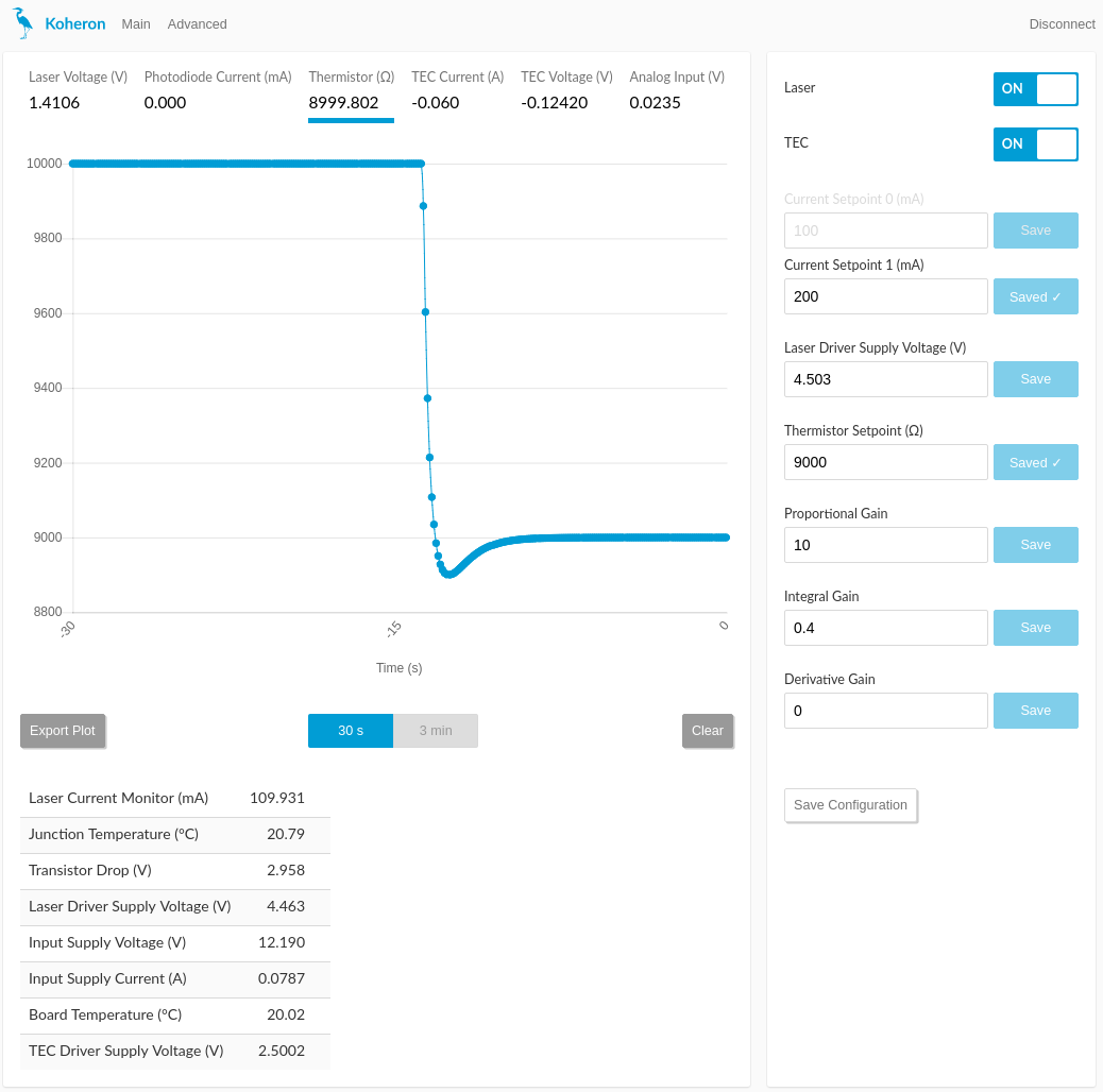
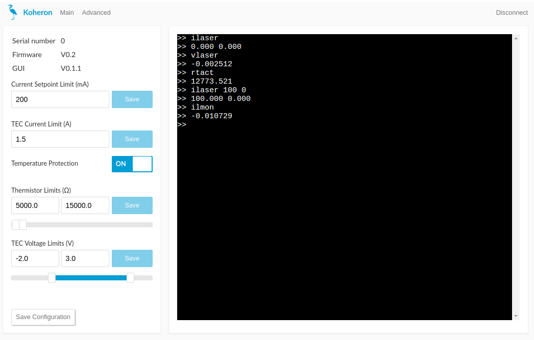
A Graphical User Interface is available for Windows. The installer can be downloaded at this link. The GUI provides an effective mean of tuning the PID gains of the temperature controller.
Control commands
| Command | Description | Type | Unit | Default | Min | Max |
|---|---|---|---|---|---|---|
| lason | Disable | enable laser current | R/W | 0 | 0 | 1 | |
| ilaser | Laser current | R/W | mA | 0.0 | 0.0 | ilmax |
| vlaser | Laser voltage | R | V | |||
| lckon | Disable | enable interlock functionality | R/W | 0 | 0 | 1 | |
| ilmon | Monitored laser current | R | mA | |||
| vslaser | Laser driver supply voltage | R/W | V | 4.5 | 1.14 | 5.1733 |
| vslmon | Monitored laser supply voltage | R | V | |||
| ldelay | Time between when the controller lights up and when the laser lights up | R/W | ms | 1000.0 | 10.0 | 100000.0 |
| ilmax | Software current limit | R/W | mA | 1200.0 | 0.0 | 2000.0 |
| vldrop | Laser driver transistor drop | R/W | V | 0.2 | 0.0 | 2.0 |
| vldauto | Disable | enable automatic adjustment of vslaser | R/W | 0 | 0 | 1 | |
| bsel | Status of the laser bias selection pin | R | 0 | 1 | ||
| tecon | Disable | enable TEC current | R/W | 0 | 0 | 1 | |
| tprot | Disable | enable temperature protection | R/W | 0 | 0 | 1 | |
| rtset | Thermistor resistance setpoint | R/W | Ω | 10000.0 | rtmin | rtmax |
| rtact | Actual value of thermistor resistance | R | Ω | |||
| itec | TEC current | R | A | |||
| vtec | TEC voltage | R | V | |||
| pgain | Proportional gain of the temperature controller | R/W | 10.0 | 0.0 | 100.0 | |
| igain | Integral gain of the temperature controller | R/W | 0.4 | 0.0 | 4.0 | |
| dgain | Differential gain of the temperature controller | R/W | 0.0 | 0.0 | 100.0 | |
| vstec | TEC driver supply voltage | R | V | |||
| tilim | TEC current limit | R/W | A | 1.5 | 0.25 | 2.5 |
| rtmin | Minimum thermistor resistance. If temperature protection is enabled, the laser current is automatically disabled below this value. | R/W | Ω | 5000.0 | 2000.0 | 50000.0 |
| rtmax | Maximum thermistor resistance. If temperature protection is enabled, the laser current is automatically disabled above this value. | R/W | Ω | 15000.0 | 2000.0 | 50000.0 |
| vtmin | Minimum TEC voltage | R/W | V | -2.0 | -4.5 | 0.0 |
| vtmax | Maximum TEC voltage | R/W | V | 3.0 | 0.0 | 4.5 |
| tjunc | TEC driver junction temperature | R | °C | |||
| iphd | Photodiode current | R | mA | 0.0 | 5.0 | |
| ain | AIN pin voltage | R | V | 0.0 | 2.5 | |
| tboard | Board temperature | R | °C | |||
| vbus | Input supply voltage | R | V | |||
| ibus | Input supply current | R | A | |||
| version | Firmware version | R | v0.2 | |||
| status | Return lason, vlaser, ilmon, itec, vtec, rtact, iphd, ain | R | ||||
| save | Save configuration in internal memory (no argument) | W | ||||
| serial | Return the serial number | R | ||||
| userdata write | Write the user data (e.g. userdata write ABC) | W | 31 chars | |||
| userdata | Read the user data | R | ||||
| brate | UART baud rate | R/W | baud | 115200 | 9600 | 460800 |
| err | Return the error code in hexadecimal format (no argument) | R | ||||
| errclr | Clear the error code (no argument) | W |
Error codes
The command err returns a 32-bit number in hexadecimal representation which concatenates the detected errors (B0 is the Least Significant Bit):
- B0: UART_BUFFER_OVERFLOW (err = 1)
- B1: UART_CMD_BEFORE_PROMPT (err = 2)
- B2: RESERVED (err = 4)
- B3: RESERVED (err = 8)
- B4: BUS_UNDERVOLTAGE (err = 10)
- B5: BUS_OVERVOLTAGE (err = 20)
- B6: BOARD_OVERTEMPERATURE (err = 40)
- B7: LASER_UNDERTEMPERATURE (err = 80)
- B8: LASER_OVERTEMPERATURE (err = 100)
- B9: LASER_OVERVOLTAGE (err = 200)
- B10: CMD_UNKNOWN (err = 400)
- B11: CMD_INVALID_ARG (err = 800)
- B12: TEC_AMP_OVERTEMPERATURE (err = 1000)
- B13: LASER_ON_WHILE_INTERLOCK (err = 2000)
- B14: INTERLOCK_TRIGGERED (err = 4000)
- B15: LASER_ON_WHILE_TURNING_OFF (err = 8000)
Adjusting the laser driver supply voltage vslaser
The CTL300E allows to adjust the laser driver supply voltage vslaser in order to optimize the voltage drop vldrop in the transistor that regulates the laser current. vldrop must stay above 200 mV for proper current regulation and below 1 V to prevent excessive heating of the transistor. In most situations, a voltage drop of 400-600 mV is a good trade-off between current regulation performance and power consumption.
An automatic adjustment mode can be enabled with the command vldauto 1. In this mode, the laser driver supply voltage vslaser is adjusted continuously so that the transistor voltage drop stays close to the value defined with the command vldrop.
Bias switching
The CTL300E allows to switch between two independent current setpoints in about 400 ns. The two setpoints are defined with the ilaser command. For instance with:
>> ilaser 100.0 600.0
100.000 600.00
The laser current will be 100 mA when BSEL is low and 600 mA when BSEL is high.
The pin BSEL is internally pulled low with a 100 kΩ resistor. If the bias switching functionnality is not needed, you can leave the pin BSEL floating and define only the first setpoint:
>> ilaser 200.0
200.000 600.00
Modulation input
DC coupled modulation input for modulation between DC and 5 MHz. Modulation range is ±1 V (50 Ω input impedance).
Thermal management
The TEC voltage limits (vtmin and vtmax) and the thermistor resistance limits (rtmin and rtmax) provide an effective way of protecting the laser against thermal runaway. For reliable operation, the aluminium cooling base plate must be properly heatsunk.
Interlock
An optional interlock functionality can be activated with the lckon 1 command. Laser current is then disabled when the LCK pin is pulled low. Once laser current has been disabled, the serial command lason 1 must be sent to re-enable the laser current. The behavior of the interlock pin can be inverted with the command lckon 3.

